
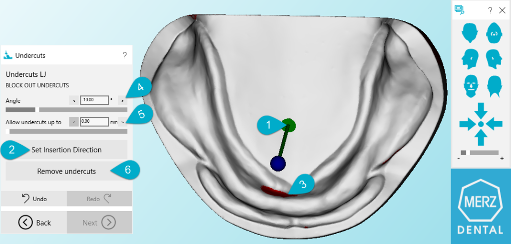
The Lower jaw model is displayed and an arrow indicating (1) the insertion direction is directed in the Z direction on the upper jaw. Then the insertion direction can be set. The arrow is changed to show directly in Z-direction of the screen.
The resulting transformation matrix must be saved in order to be applied (2) in the calculation of undercuts.
After the insertion direction is set, the areas that need to be removed/blocked are shown in false colors (3).
In this step, all the undercuts which are recognized by the system, are color-coded.
You can decide by means of the parameters offered, the extent to which the undercuts shall be removed (4 or/and 5).
Angle (4) and retention (5) of undercuts may be defined by moving the sliders in the wizard. After changing a parameter and releasing the mouse the calculation is immediately applied.
The default values can be defined in a configuration file.
When clicking on “Remove Undercuts” (6) the model is changed according to the selected parameters.
A dental technician removes undercuts by adding material (wax) to the dental model, as shown in the image below.
Figure 1 Blocking out Undercuts

Figure 2 Undercuts without parameters. On the digital side, the CAD software removes undercuts as follows: You define an insertion direction, as outlined with the red line in Figure 1, where the CAD blocks out undercuts in a tooth shape. In the real world,material would be filled up in this zone, (blue colour in left image). In the CAD, currently, the surface in the undercut region is removed, and replaced by a surface that is along the insertion direction.

Figure 3 Undercuts with angle (0-50)
The CAD permits a parameter, namely an angle. Again, the red line in Figure 2 shows the insertion direction. The purple line shows the addition of an angle to the insertion direction (Angle can be from [0,50]). The blue on the left illustrates the material being filled in the analog process by a dental technician. The right pictures illustrate the outcome after the operation. Again, the zone of undercuts with the angle correction are removed, and a new surface is inserted along the insertion direction corrected by the angle.

Figure 4 Undercuts allowed up to .5mm. For the technical dental reason, a dental technician might need a small amount of undercut areas. Figure 4 shows an example, where the insertion direction is implemented in red, we have an additional angle, resulting in the purple line.
Would there be only the angle, we would fill up as in Figure 3. But since we allow undercuts up to 5mm, the CAD would measure the distance between the newly inserted surface, and the old surface (see the black horizontal line in Figure 4). The CAD allows undercuts up to the entered parameter, (for example 0.5mm), then proceed for the remaining surface as was done in Figure 3
